Category Archives: Build Projects

System Build : Summer 2016- January 2017

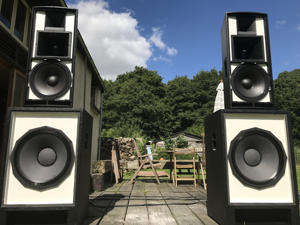
Thought we’d share a few pictures from one of our happy customers who we assisted with putting together a PA system. Our customer was looking for a unique look, high quality, good value for many and a DIY project that wasn’t too taxing. We assisted by providing a number of options and suggestions, as well as help and support during the build.

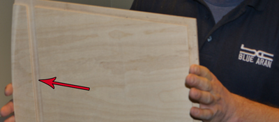
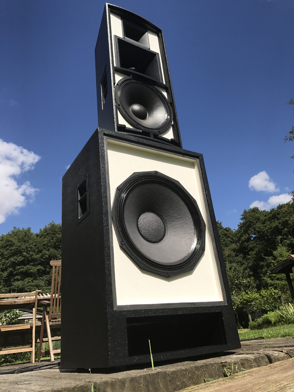
Sub-Bass: The decision was made to take a no-compromise approach to the bass section, and the Precision Devices PD.2150 was chosen for this application. Following the guides from the Precision Devices website, (http://www.precision-devices.com/Downloads :: http://www.precision-devices.com/file-downloads/PD-EnclosureDesignGuide-1.pdf ) our customer completed the first part of the build project with minimal assistance from us, and with a couple of tubs of Tuff Cab speaker paint was able to build himself a serious pair of subs, with his own choice of black and white finish.

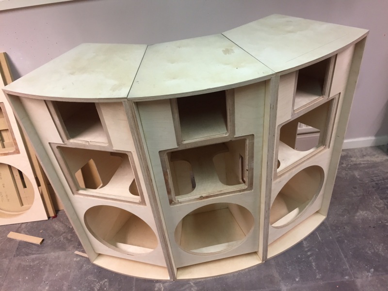
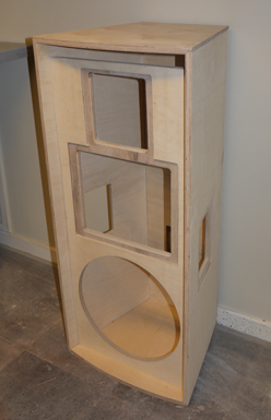
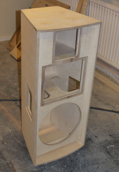
To complete the system, we helped guide our customer towards the solution that was right for him. With the specification requiring high quality, controlled dispersion, good projection, and smooth mid-tones, the JAM Systems 1581 3-way cabinet was chosen as the best option.

Utilising the MR8XT mid-range horn, the 1581 is a 3-way cabinet that takes advantage of a high sensitivity 8″ cone driver in a custom horn, with dedicated phase plug and moulded back bowl. This complete all in one unit is available exclusively from Blue Aran:  http://www.bluearan.co.uk/index.php?id=SONMR8XT

This unit was made available in Autumn 2015, and we designed a 3 way cabinet around the MR8XT, with a 15″ Mid-bass unit, running below 400Hz, and a 1″ Compression driver above 2.5kHz


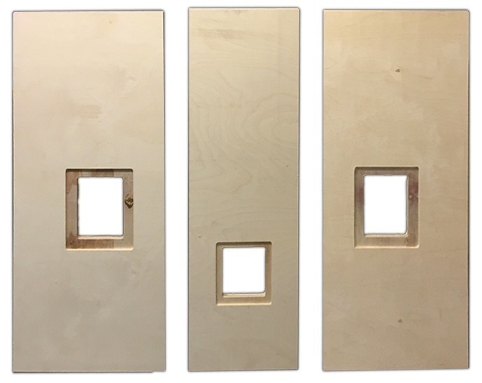
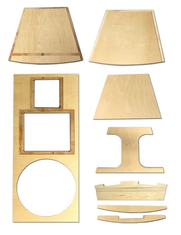
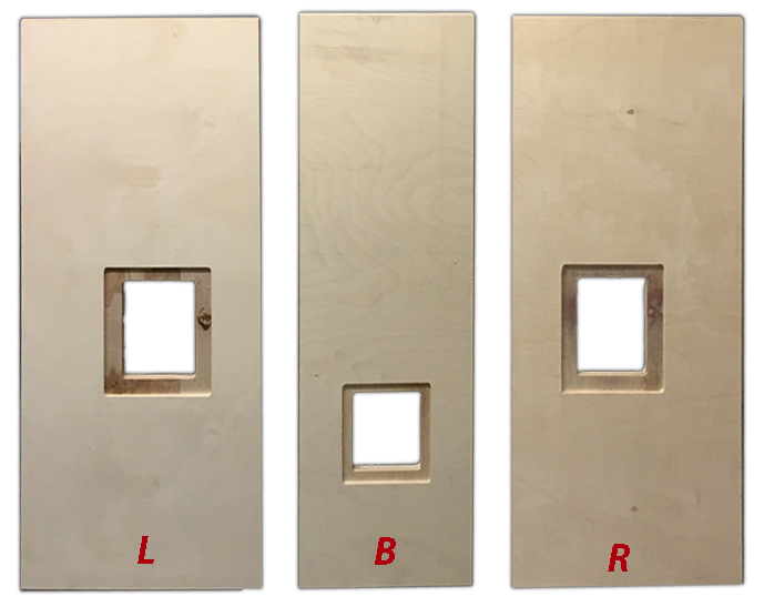
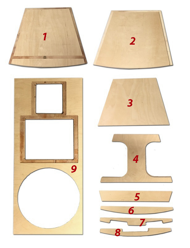
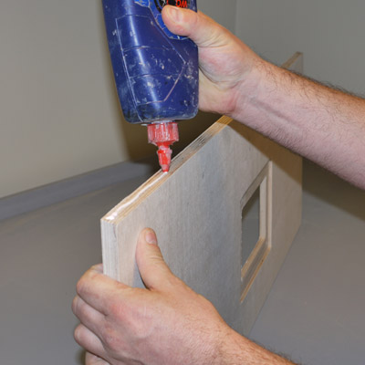
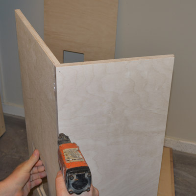
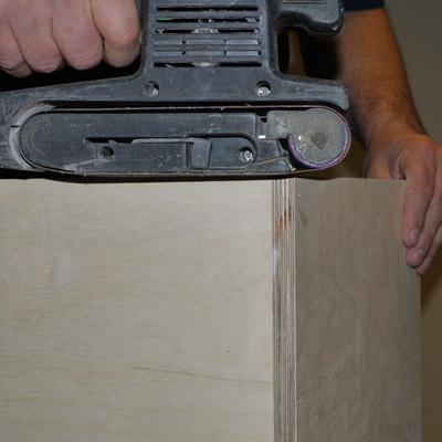
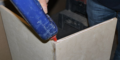
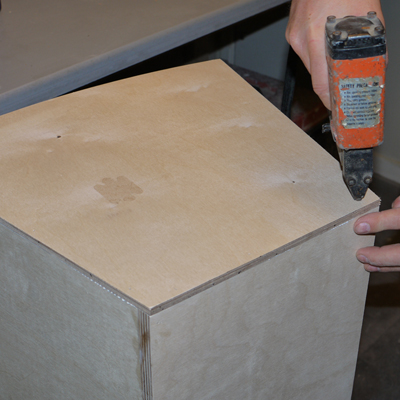
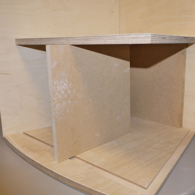
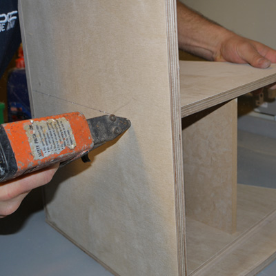
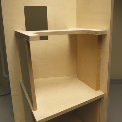
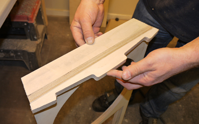
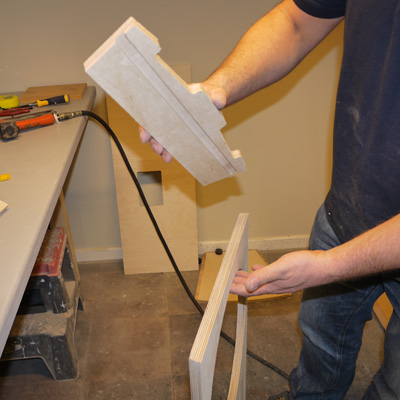
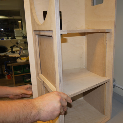
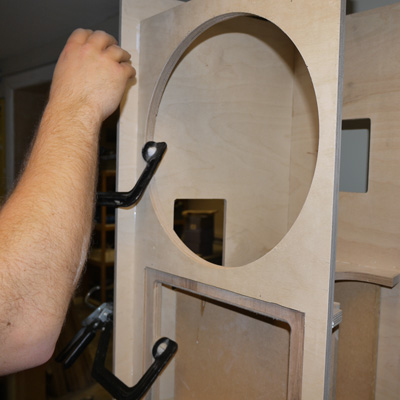
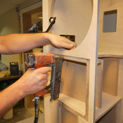
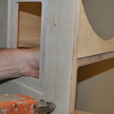
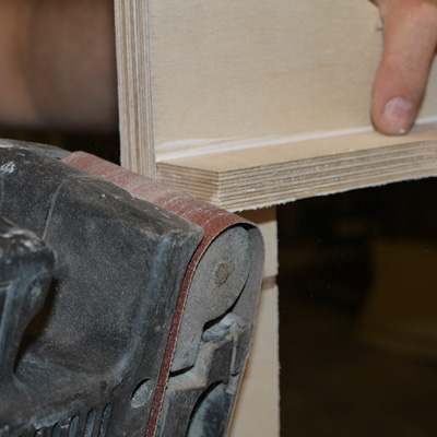
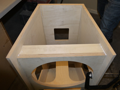
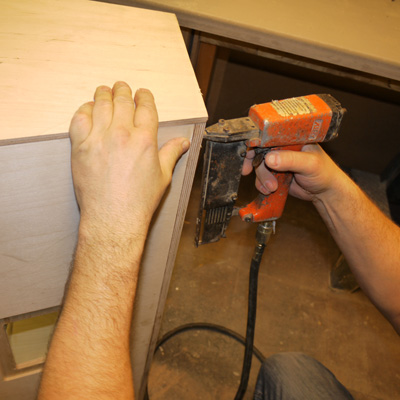
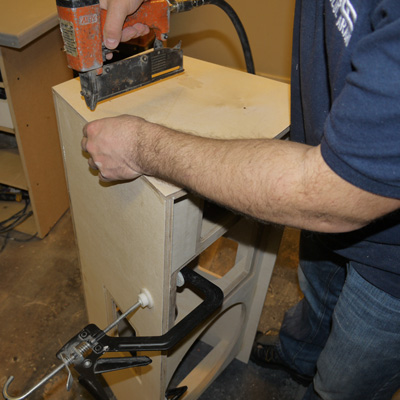
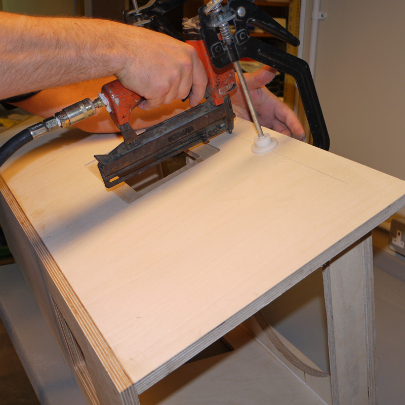
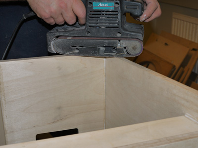
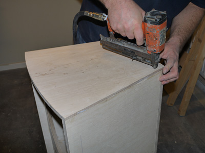
The 1581 kit is intended as a DIY project and is available in flat pack form for self-assembly. Assembly required basic woodworking skills only; all the panels are accurately cut with CNC machine and feature rebated joints. Glue and nails or screws are all that’s required. Assembly instructions provided.


For this build, premium quality components were selected:

For mid-bass, the B&C 15NDL88 was selected. This is a high power 15″ driver with a medium weight cone, offering fast, tight, punchy bass and excellent sound quality. A neodymium magnet helps keep the weight low.

For the mid section, the lightweight mid horn, MR8XTN offers a weight saving over the standard MR8XT, with no compromise on quality.

To match the MR8XTN, the Beyma TD164  offers the perfect combination, of size, shape, dispersion and strength. 60 x 40 dispersion and sturdy aluminium construction make this the optimum choice.

Finishing off the system is B&C’s trusty DE250 offering a great combination of sound quality and value for money


It is possible to customise the 1581 system, using alternative 15″ drivers. We recommend at least 500W and a ‘medium’ cone – not too heavy and not too light. The 15″ isn’t handling sub, so a medium weight cone will be more responsive and give a more punchy mid-bass. Since the majority of the quality of the sound comes from the 8″ and 1″, the choice of 15″ is not critical to the overall tone, but good power handling is essential in order to keep up with the high sensitivity 8″. Choice of 1″ is down to personal preference, we find the DE250 is a very versatile compression driver that lends itself to many different styles of music.

It’s possible to run the 1581 in 3-way configuration, with a seperate amp for mid-bass, mid and high channels. This requires 8 pole speakons, more amps and overall a more complex system. To help keep things simple, we developed a simple 2-way passive crossover which can be inserted between the 8″ and 1″ . Our standard crossover has been tuned to work with the DE250 compression driver, and includes some subtle EQ to get the best out of the speaker with minimal effort.

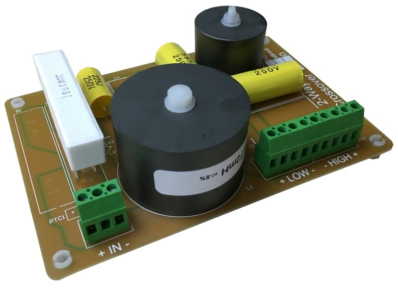
To balance the 8″ and 1″, there is approximately 3dB attenuation on the high pass circuit, with a capacitor bypass to create a hi-shelf at around 9kHz. This gives a slight lift from 9kHz which is where the DE250 begins to naturally roll off a little. The capacitor is in parallel with the attenuation resistor, which means only lower frequencies are attenuated.


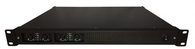
The passive crossover allows 4 pole speakons to be used on the cabinet, saving money on amplifiers, and cabling. To complete the system, we supplied one of our custom amplifiers: the JAM Systems B8  which has been specifically designed for bi-amp operation with complimentary high power and medium power channels pre-wired  ready for bi-amp operation, eliminating the needs for extra patch panels. Channels 1 and 2 are high power and medium power, and are pre-wired onto all 4 pins of output speakon 1. Just connect straight into the 1581 and you’re ready to go.

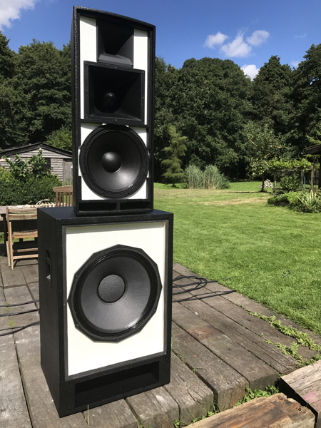
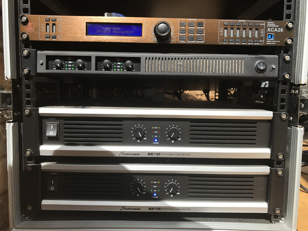
The complete system is shown below, starting at the top is a dB-Mark XCA26  which we supplied pre-configured for the system. Followed by the JAM Systems B8 running the 1581s, and finally a pair of Studiomaster AX35s, each one bridged into PD.2150


Here’s what our customer thought:


You supplied me lots of kit over the winter to build my new system, which at last is finished! I can’t believe how good it sounds, and how pleased I am with the quality and output of the JAM speakers supplied by you. I have not played it to anyone who has not been mightily impressed! 
Can’t thank you enough for all your detailed advice and steering me down this road. The JAM package destroys similar cost main brands – different league…

Assembly instructions for JAM Systems 1581 Flatpack speaker kit

JAM Systems 1581 Flatpack Speaker Kit – Introduction


Before starting work, please check you have all the correct parts for this project:

Parts List:

1. Top panel

2. Bottom Panel

3. Internal Divider

4. Internal Brace

5. Reflex Port

6. Grill Support

7. Grill support *** mk2 version parts 5 and 7 are one piece for easier assembly ***

8. Middle Grill Support

9. Front baffle

L. Left Hand Panel

B. Back Panel

R. Right Hand Panel

This is a DIY Flatpack project, all the parts are pre-cut which saves a lot of time and effort – however you will still need reasonable wood-working skills in order to complete this project. We have suggested recommended tools which are appropriate for use for this project. Ensure you use appropriate personal protective equipment at all times, and check all your tools are safe before proceeding. It is your responsibility to ensure you use these tools in a safe manner, if you are not confident in using these tools, please consult a professional for training and/or advice.

Recommended tools:

Air compressor with Nail Gun. This enables very rapid assembly – if you dont have access to one of these, you will need appropriate drills, drill bits, screwdrivers and screws. The packs are not pre-drilled, you will have to select appropriate screws and relevant bits as appropriate.

Belt Sander. All the parts are cut to size, but a little fine tuning may be required and a belt sander is the ideal tool. It is possible to assemble without a belt sander, but you will most likely need some form of sander (fairly coarse) to adjust panels for a perfect fit. If you dont have a sander at all, the best solutiuon will be to ensure you have a plentiful supply of glue and use a generous amount on all joints to ensure any slight gaps are filled.

Clamps. We use single handed quick clamps – these are very useful for hold parts in position while assembling. Any suitable clamp will do the job, but the single handed ones work great in this situation. You can still assemble without any clamps, but you will find some parts of the assembly quite challenging, and you may find it useful to have an extra person to help hold things.


READY TO START?

Take a couple of minutes to familiarise yourself with the parts, and dry-fit them in position without any glue, nails or screws – just check they fit together as expected (see picture). Each part needs to be positioned the correct way around in the correct place or your assembly will go wrong.

In the image on the left we have just placed the panels in position, resting against the wall, to confirm it is a full set of parts.

The connector panel cutout on the rear panel should be towards the bottom of the cabinet, and the handle cut outs on the left and right panels are slightly nearer the front of the cabinet and in the lower part of the cabinet roughly at the centre of balance. If you get the left and right panels the wrong way around the handles will be too high up.

When you’re familiar with the parts, move on to Part 2 of the instructions


ASSEMBLY INSTRUCTIONS

Step 1:

Start with one of the side panels, eiher the LEFT (L) or RIGHT (R) panel. In the photos here we used the right panel. The rear edge of this panel is cut at a 12.5° angle, apply a bead of glue to the angled edge.

The handle cut out will be closer to the front (90°) edge, and closer to the BOTTOM of the cabinet.


Step 2:

Ensuring the connector cutout on the back panel is nearest the bottom, with the recessed rebate facing outwards, attach the rear panel to the side panel. Align the edges to be flush as you work your way down from one end to the other.

These panels are the same length, so the ends should also be flush with each other. Where the panels are quite tall, you may find it easier to do this step on the floor, which will also help align the panels lengthways if you have a level flat surface.


Step 3:

Check the top edges of the two panels, they should be flush with no lip. If during assembly one panel is slightly higher than the other, you should sand this to make it flush across the two panels. This will help with ensuring the side and back panels line up correctly with the top panel.


Step 4:

Apply a bead of glue along the top edge of the rear and side panels. From now on you should assume that all joints require a generous bead of glue, and this instruction may be omitted in future steps.

Step 5:

Fetch the TOP panel (1) – note that this is different to the bottom panel as it has an extra rebate that the front panels fits in. The top and bottom panels ARE NOT interchangeable.

Step 6:

Fit the Top Panel to the Rear and Side panels using nails or screws as preferred.

Surplus glue should ooze out from the joint as you screw/nail.

Once you have affixed the top panel securely the speaker is starting to take shape, and is strong enough to be moved around. Its best to do the next step on a table or workbench, so carefully lift the three assembled panels and turn the structure upside down so that the TOP panel is resting on the workbench.

Step 7:

The divider panel (part 3) is next, this needs to be fitted with a distance of 227mm between the divider and the top panel. The easiest way of properly aligning the divider panel is by resting it on pre-cut spacers.

We can supply spacers if required – please ask, these are free of charge.

These spacers are temporary, and are removed before assembly is complete, take care not to glue or pin the spacers as it will make them difficult to remove later

Step 8:

Pin through the side and rear panels into the divider panel. You may find it useful to draw a guideline to indicate the middle of the divider, this should be 250mm from the edge (the 250mm spacer for Step 9 does the job nicely for drawing a guideline)

This is a good time to check everything is lining up correctly, if you offer the front baffle into position, the divider should line up approximately to the edge of the 8″ horn cut-out.
.

Step 9:

The next step is to fit the central brace (4). Two spacers 250mm high will position the divider appropriately. Again, we can offer these free of charge if needed, please ask. Remember, the spacers are temporary, so take care not to glue or pin them.

Apply glue to the mating faces of the brace and push firmly into the corner before pinning the panels together from the outside.

Step 10:

Leave the partially assembled cabinet to one side whilst you prepare the front baffle. The port needs to be fitted before the baffle is fitted in the cabinet. The port goes on the BOTTOM of the front baffle, below the round cut out for the 15″ driver. The updated mk2 kits have combined pieces 5 and 7 into a single part which acts as both port and grille support, this is shown in the picture.

Step 10: (mk2)

The updated mk2 kits have combined pieces 5 and 7 into a single part which acts as both port and grill support. Locate the front baffle in the rebate, and then pin through this panel into the front baffle.

After fitting, check the sides of the port are flush with the front baffle, sanding as required

Step 11:

Leaving the spacer supports in place, check the front baffle fits correctly. Do not rush this part as it takes care to get this right. All previous joints have been simpler to assemble as you are generally working with only 2 parts at a time. Here you need to ensure the front baffle fits snugly against the side panel, the brace, the divider and the top panel (currently at the bottom as the cabinet is upside down). There is very little wood around the sides of the round cut-out of the 15″ driver, take care not to bend the front baffle when assembling. You may find it useful to draw a line on the inside of the side panel using a long straight edge to ensure you keep the front baffle straight.

This is a critical stage in assembly, is is very important not to rush this. Take a good look at what you are doing before you attach panels.

Step 12:

Once you are confident everything is in the correct position, apply glue to all faces that are to be attached.

Push the front baffle firmly into place, and whilst checking the baffle remains straight, clamp the baffle to the side panel in two places, inside the round cut out, and inside the 8″ horn cutout.

Before proceeding, double check everything fits snugly and there are no unexpected gaps. Its very hard to adjust anything after this stage if you get it wrong. Make sure you push down so that the baffle is sitting in the rebate in the top panel.


Step 13:

Start by pinning the front baffle to the brace and the divider, whilst pushing the front baffle firmly into place.

Before proceeding, check again that everything fits snugly and there are no gaps.

For step 14 you may find it useful to mark the outside of the side panel with a guide line 40mm in from the front edge. This is not essential, but this will make pinning the side panel to the front baffle easier, and help ensure you apply pins in the correct position.


Step 14:

Move on to the side panel and pin at intervals between the clamps. Once the side panel is firmly fixed to the front baffle in a few places, you can remove the clamps and continue fixing the two panels together securely.

Take care around the 15″ round cut out, its best to avoid pinning here at the narrowest point, just leave it for the glue to set and form the bond here.

Once all the other panels are secured, turn the cabinet around so that you can pin through the top panel into the front baffle.

Step 15:

You must now remove all the support spacers, as it will be impossible to get them out once the second side panel is fitted.

Before proceeding check the positioning of all the other panels. The divider shelf and brace on the exposed side should be flush with the front baffle, sand as necessary to ensure they line up.

At this point you still have good access to the inside of the cabinet, this is the perfect opportunity to run a thin bead of glue along the inside of any corners that may need it. If you’ve been applying this generously as you go along you may not need to do this. Use a slightly damp cloth to wipe up any excess glue.

Step 16:

We’re getting close to finish, but don’t rush – it’s important to make sure the second side panel is fitted correctly, and as before, be careful with the front baffle to avoid bending it across the round cutout for the 15″ cutout.

Apply generous beads of glue to all faces that will be fixed together. Place the side panel in position, pushing it firmly into place against the divider and brace, and then clamp it against the front baffle. Check carefully that everything lines up and there are no gaps between panels..

Step 17:

There is a little variation with any natural product such as wood. The kit is designed to fit together allowing for this, and providing you assemble in the order specified in these instructions all the panels should fit snugly together, leaving in some cases a slight lip (typically less than 1mm) on the top and bottom panels and the second side panel. This is intended to be sanded or planed off afterwards, and is a better option than having to fill gaps.

Before pinning the side panel, place the bottom panel in position – this will help ensure to align the the side panel in the correct position. In the picture the bottom panel is just held in place with light finger pressure. Start by fixing the rear panel to the side panel.

Step 18:

After fixing the rear panel to the side panel, manipulate the box the other way up so that you can pin the top panel into the second side panel – do not pin the bottom panel in place yet.

Leave the clamps in place between the side panel and front baffle whilst you are doing this.


Step 19:

Continue working around the box and pin the side panel to the front baffle, the internal divider and brace. Drawing guidelines will help with locating the pins. Again, keep the clamps in place until you have started pinning the side panel to the front baffle, and avoid pinning near the narrow part of the baffle.

Before proceeding to the final stage check all panels have been pinned and glued as appropriate.


Step 20:

There is just one panel left to finish the main assembly of the cabinet, as mentioned previously, there is sometimes some natural variation in wood, and it is also possible to assemble panels slightly out of alignment. Before fitting the last panel, check the corners and sand as appropriate to ensure a close fit.

Whilst you still have easy access to the inside of the cabinet, check all joints have appropriate glue. Either add a bead of glue, or wipe away excess as appropriate.

Step 21:

Apply a bead of glue and then pin the bottom panel into the rear, left and right panels.

The bottom panel is not connected to the front baffle due to the slot port.


Step 22: Finishing

The main cabinet is now assembled, just the finished left to do. If you’ve made it this far, hopefully you dont need any further instructions, but here’s a quick summary of what we do:

1. Allow the glue to dry, and then use a belt sander (or similar) to smooth all joints.

2. Use non-solvented (water-based) wood filler to fill all screw holes or nail holes. Mix in a little wood glue with the filler to make it stronger.

3. Sand over all the filled areas.

4. Using a router and roundover bit, carefully go around all the edges of the cabinet. If you dont have a router, run a belt sander over the edges to smooth them off a little.

5. Check the surfaces of the cabinet carefully to ensure they are free of dirt and dust, ready for painting. After sanding its a good idea to use a slightly damp cloth to wipe the surfaces, this helps remove fine particules of dust.


Optionally, you can change the order of assembly slightly, and leave the front panel till last, after assembling all the other panels. This is a matter of personal preference and is dependent on your woodworking skills with regard to making fine adjustments with a sander or similar tools to ensure a good fit on the dividers, braces, and that the front baffle sits securely and is square without any bending or bowing.